[WooreeINFO] MicroEJ Studio - MicroEJ Firmware for LPCXpresso54628 does not boot up

Dear MicroEJ,

When i tried to reproduce the steps specified in the URL of http://developer.microej.com/gcp-nxp-getting-started-iot.html earlier today, i don’t feel the device boot up correctly and i think i need your assistance - based on your courtesy.

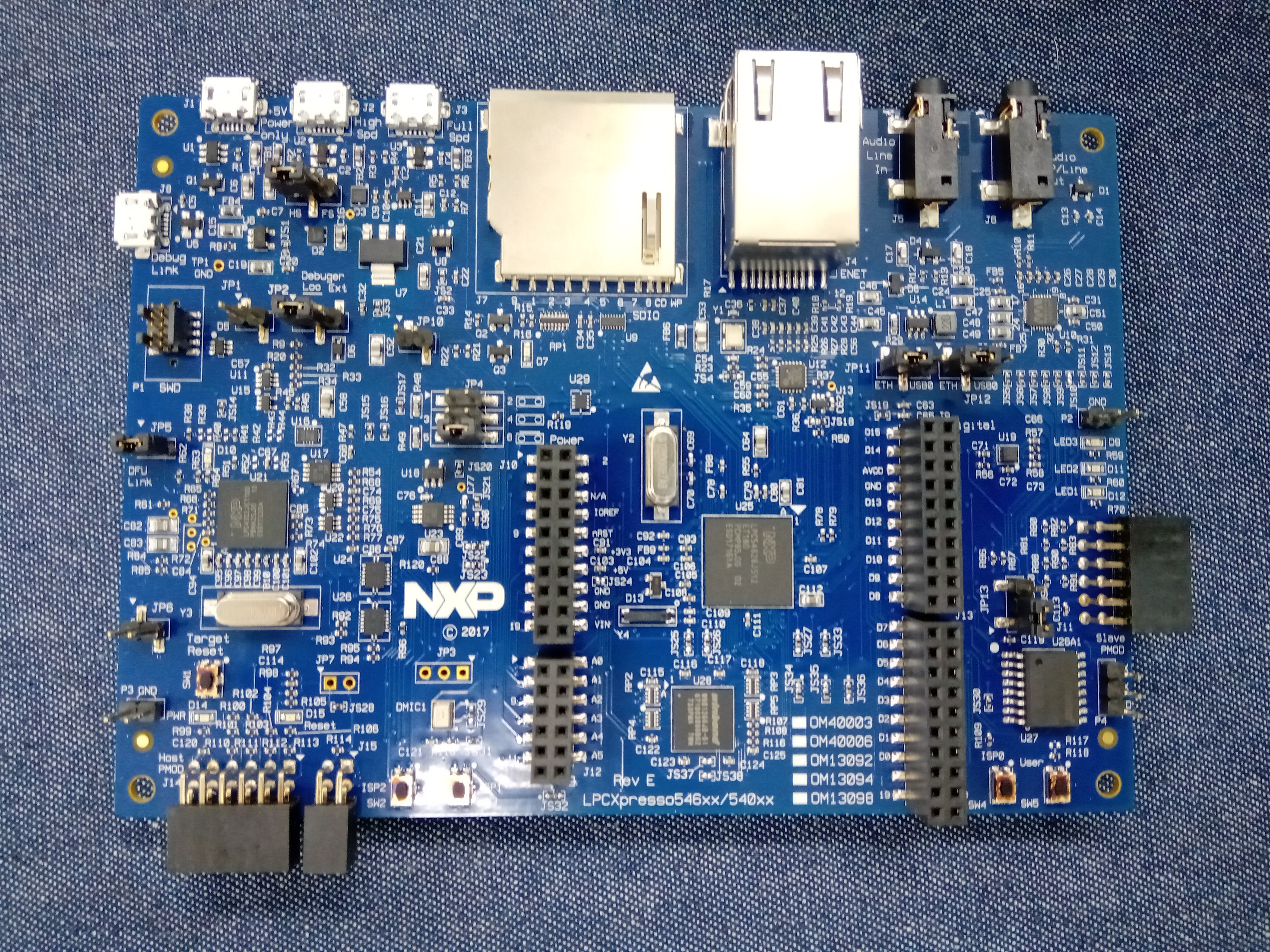
i’d like to share more details about my current status, mostly based on the attachment(.GIF picture), as:

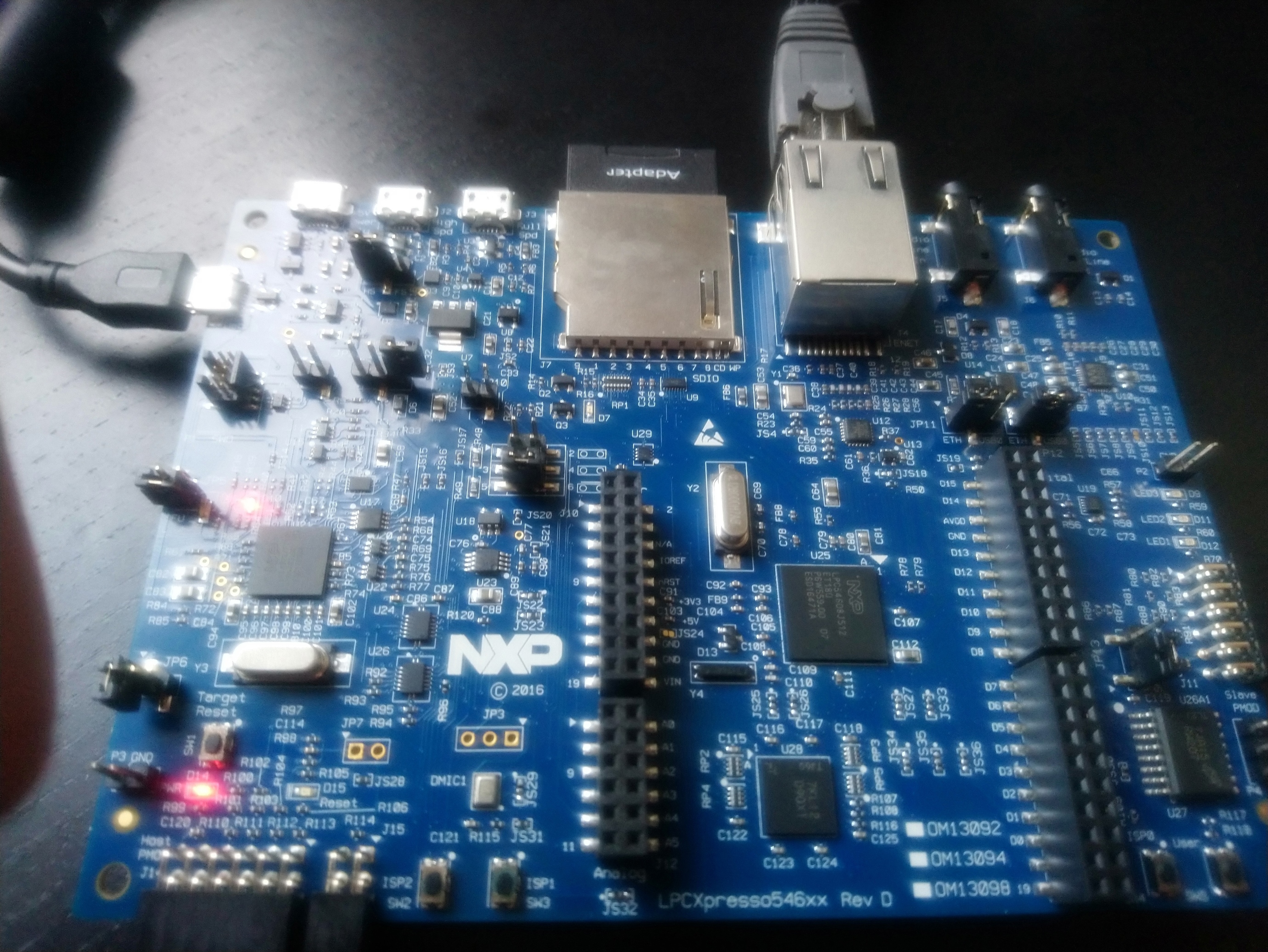
My NXP board is LPCXpresso54628, slightly an upgrade of your reference , however i see the comments by NXP in their website as:

“The LPCXpresso54628 is binary backward compatible with the LPCXpresso54608 and LPCXpresso54618 boards.” (OM13098 | LPCXpresso Development Board | LPC Microntrollers (MCUs) | NXP Semiconductors)

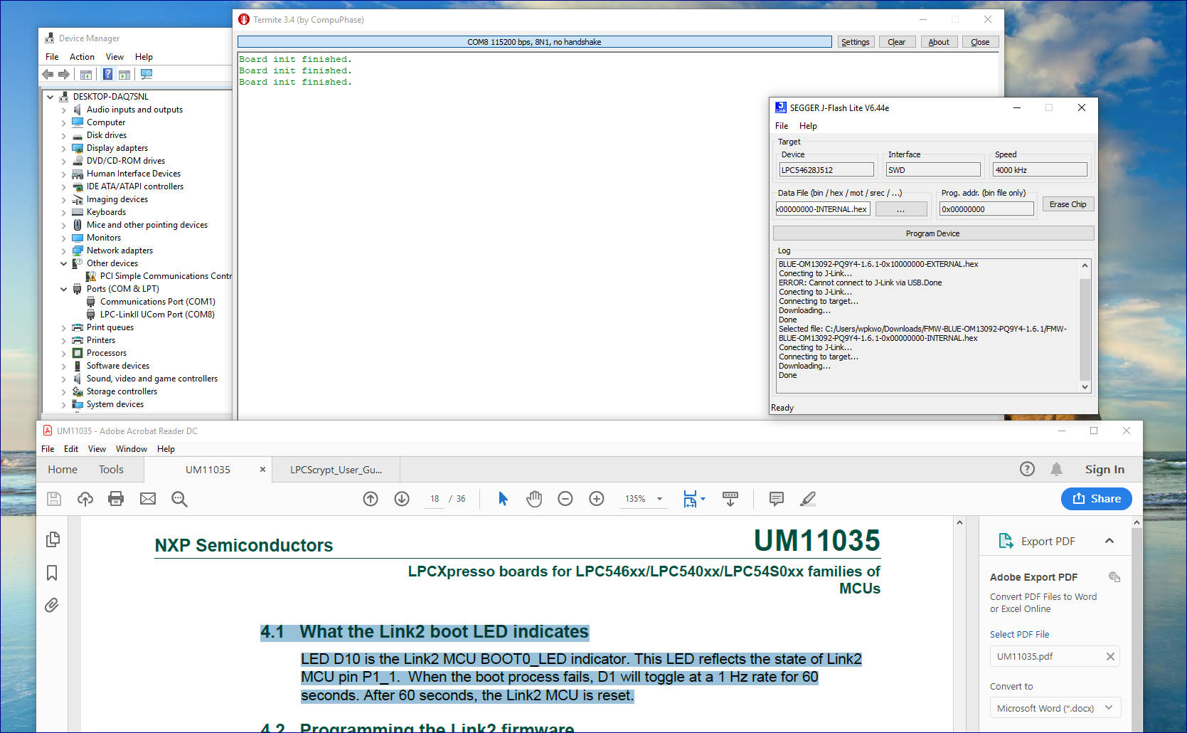
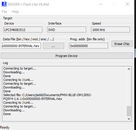
Then, i chose the device of and also the speed of <4000KHz> in the step of . There was no failure while flashing the external and internal .hex files.

When i ran the script of <program_CMSIS.cmd>, after flashing, i see the serial port with its name of <LPC-LinkII UCom Port(COM8)>.

When i pushed the reset button, the serial terminal(Termite) showed the message of “Board init finished.” with nothing else.

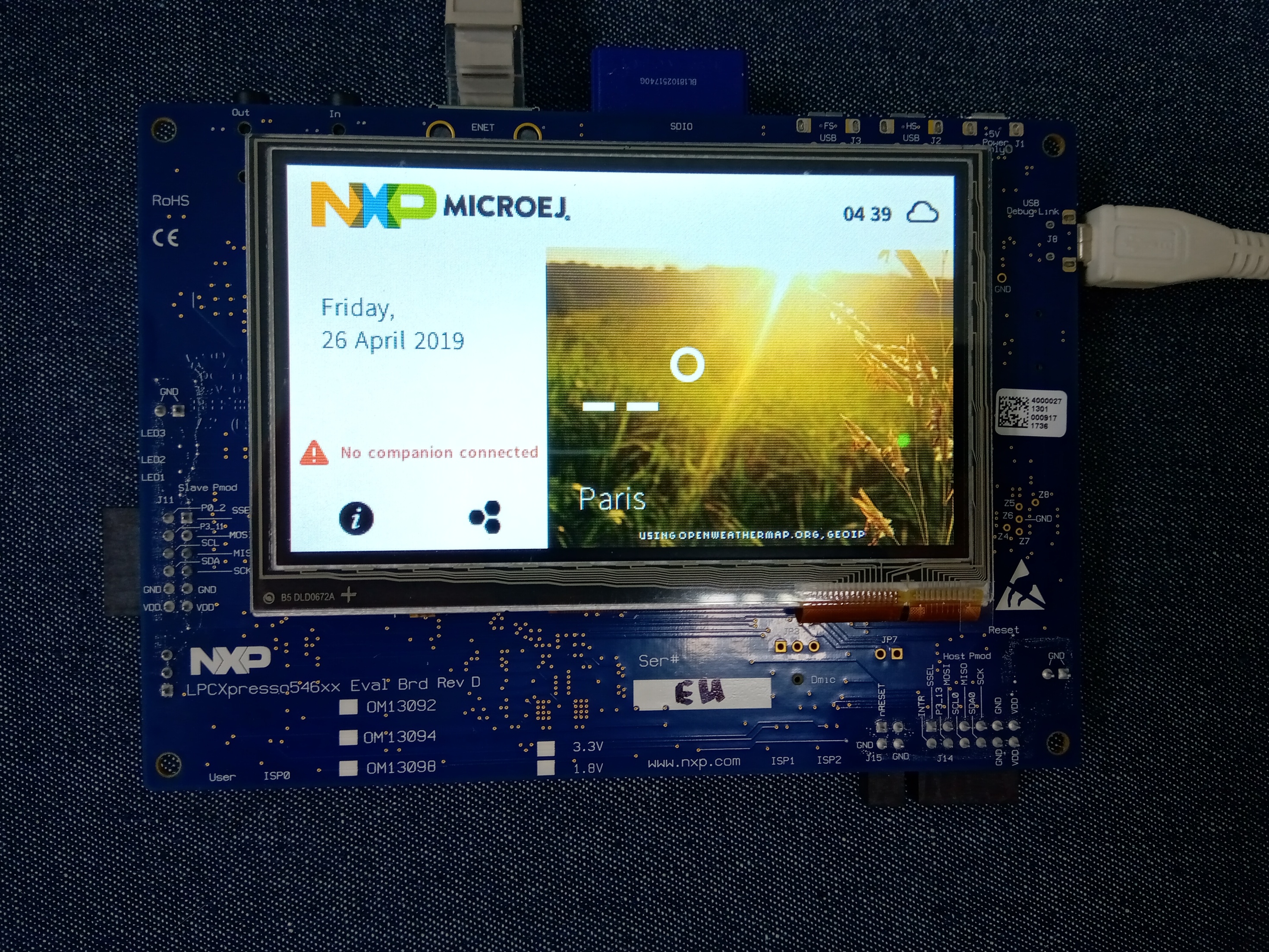
The NXP device shows nothing on screen.

The LED D10 in the NXP device is blinking mostly every second as i think; which means:

“LED D10 is the Link2 MCU BOOT0_LED indicator. This LED reflects the state of Link2 MCU pin P1_1. When the boot process fails, D1 will toggle at a 1 Hz rate for 60 seconds. After 60 seconds, the Link2 MCU is reset.” (https://www.nxp.com/docs/en/user-guide/UM11035.pdf)

My NXP device is connected to Ethernet, and the router shows a green led on it.

My NXP device has an SD Card inserted, which is formatted with FAT32.

Thanks much in advance for your cooperation.
YH Kwon

Dear @kwonyh,
unfortunately, we have validated our firmware only on the LPCXpresso54608 Development Board. We advise you to get a card to do your tests.
On our side, we will get the other 2 card references to validate our firmware as soon as we can.

Best regard,
Jerome S.

Dear @kwonyh,
I have found in our boxes an LPCXpresso OM13098 board version with a LPC54608 MCU and LPCXpresso OM13095 board version with a LPC54628 MCU.

On these 2 boards, the firmware starts but you must burn the flash with JFlash Lite configuration for LPC54608J512 at 1000Khz.

Could you try this please.

Best regards,
Jerome S.

2019-04-12%2017_19_06-Window

Dear Jerome Siddi,

Thanks for your feedback first of all, and please find my additional feedback/comments as:

[1] Your suggestion

>I have found in our boxes an LPCXpresso OM13098 board version with a LPC54608 MCU and LPCXpresso OM13095 board version with a LPC54628 MCU.
>
>On these 2 boards, the firmware starts but you must burn the flash with JFlash Lite configuration for LPC54608J512 at 1000Khz.
>
>Could you try this please.
>

[YH@4/15/2019] i tried with your suggestion above, but there was no success for me unfortunately. Even when i tried with another board of the same purchase and also with the latest J-Flash Lite, dated as Apr. 12th, 2019, i didn’t get a success at all.

Please take your review on my further observation below, where you might find a clue so as to advise me as i hope.

[2] LED 'D7’

The document of ‘UM11035: LPCXpresso546x8/540xx/54S0xx Board User Manual’ from NXP says about ‘D7’ as:

>SD card slot power enable
>This LED illuminates when power is enabled to the SD card slot (controlled by LPC546x8/540xx/54S0xx port P2-5.)

However i see this LED ‘off’ once i have flashed your firmware(external & internal).

i see this LED ‘on’ at the time as:

a> once i ran ‘program_JLINK.cmd’ for flashing your firmware.

b> once i have flashed ONLY the external firmware of v1.3.6; which is an older one than the one described in the URL(http://developer.microej.com/gcp-nxp-getting-started-iot.html) and that i found at your ‘developer’ page.

c> once i have done ‘Erase Chip’ with J-Flash Lite.

[3] LED 'D10’

The document of ‘UM11035: LPCXpresso546x8/540xx/54S0xx Board User Manual’ from NXP says about ‘D10’ as:

>Link2 boot mode
>Link2 LPC43xx BOOT0_LED indicator. Reflects the state of LPC43xx Link2 MCU P1_1. When the boot process fails, D1 will toggle at a 1 Hz rate for 60 seconds. After 60 seconds, the LPC43xx is reset.

i see this LED flashing mostly like the description above ONLY when i tried the steps at “8> Advanced Settings” for debug traces.

Before doing this, i see this LED flashing very fast - much faster than the description above.

Please advise me further about anything else i need to try, and i’d like to appreciate you once again for your valuable feedback.

Regards
YH Kwon

Hi @kwonyh,

Thank you for this informations.

[1] if that can help you, here are the details of my test setup :

  • firmware version: 1.6.1

  • JFlashLite version: V6.44d

  • Flashing parameter : Device = LPC54068J512 ; Interface = SWD; Speed = 1000 Khz

  • Board 1: PCB version LPCXpresso546xx Rev D ; MCU LPC54608J512
    Board 2: PCB version LPCXpresso546xx Rev C ; MCU LPC54628J512

  • Jumper configuration:

Please, could you give me all identification elements of your board ( PCB version, MCU part number, serial number,…) ?

Dear Jerome Siddi,

i’d like to appreciate for your feedback first of all, and please find my email to support@microej.com where you can see my feedback in the attachment(.PPT).

Please be advised that all the embedded photos, in the .PPT document, are also in the .zip archive - just for the higher-resolution ones that you might need.

Thanks & Regards
YH Kwon

Dear Jerome Siddi,

When i tried this with one of the NXP LPCXpresso54608 Rev. D boards, newly purchased, your firmware works fine and i’m working on the Java application porting now.

Hopefully you can pursue this problem further for us because we’d like to use the NXP LPCXpresso54628 boards as well once our java application porting is done.

Thanks & Regards
YH Kwon

Dear Jerome Siddi,

Do you have any update on your validation with ‘NXP LPCXpresso54628’?

FYI, this may NOT be a big hurry even if i’d like to understand first where the problem was and also to see if i can use these development boards for our biz.

Thanks & Regards
YH Kwon

Dear @kwonyh,
please can you check if the JS37 and JS38 jumps are open on your board?

Best regards,

Jerome S.

Dear Jerome Siddi,

Thanks for your feedback on LPCXpresso54628 first of all, and those pins are still open as it was delivered from the factory as:

7.7 Smart Card (revision E and onwards only)

Smart Card 0 interface connections are routed to J10 pins 13 (P0_20) and 15 (P0_21) via solder jumpers JS38 and JS37. Since these signals are also used for the EMC (SDRAM) address lines A2 and A3, these solder jumpers are left open by default. If these solder jumpers are closed, then care should be taken not to access the SDRAM and thus cause bus contention.

(copied from UM11035.pdf)

Just FYI, please find a photo for my board in the attachment which was taken just now for you. You need to look at the bottom-center of the photo, which is just above the printed word of <LPCXpresso546xx/540xx>.

Thanks & Regards
YH Kwon